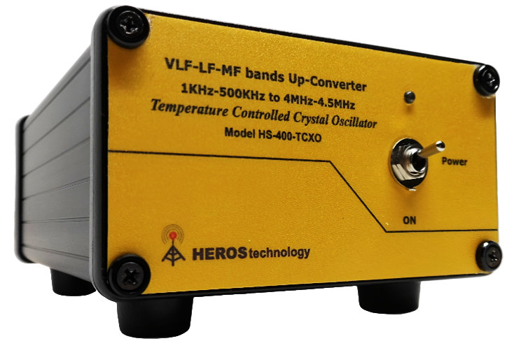
Introducing the new VLF-LF-MF bands Up-Converter HS-400 TCXO
Temperature Compensated Master Crystal Oscillator
Range DC to 530kHz.
The HS-400 TCXO front view
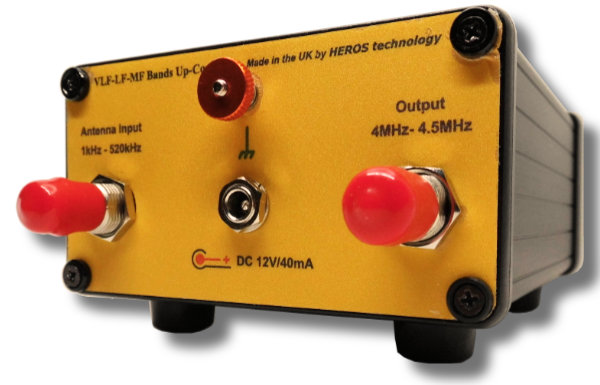
The HS-400 TCXO rear view
VLF-LF-MF bands Up-Converter HS-400 TCXO Overview
The HS-400 VLF-LF-MF Up-Converter extends the range of any shortwave receiver from DC to 530 kHz. Given the limited availability of radio receivers on the market that effectively cover these frequencies, we at Heros Technology, have developed a high-performance VLF-LF-MF Up-Converter to fulfil this need. We are pleased to introduce this innovative solution to our customers, ensuring they have access to a reliable and efficient tool for their listening requirements.
The VLF-LF-MF Up-Converter HS-400 TCXO is ideal for professional applications and radio enthusiasts listeners alike. It facilitates the reception of extremely low to medium radio frequency signals, ranging from DC to 500 kHz. This radio spectrum of frequencies covers radio services such as maritime communications, aviation, and marine navigational aids, including Non-Directional Beacons (NDB) and Differential Global Positioning System (DGPS) beacons, DGPS reference stations, NAVTEX, standard time and frequency stations, LF amateur bands, European long-wave broadcast stations, and monitoring of natural sounds generated by planet Earth (Natural Radio). These natural sounds include phenomena such as sferics, hiss, tweaks, whistlers, Dawn Chorus, and other lesser-known VLF radio geo-atmospheric phenomena.
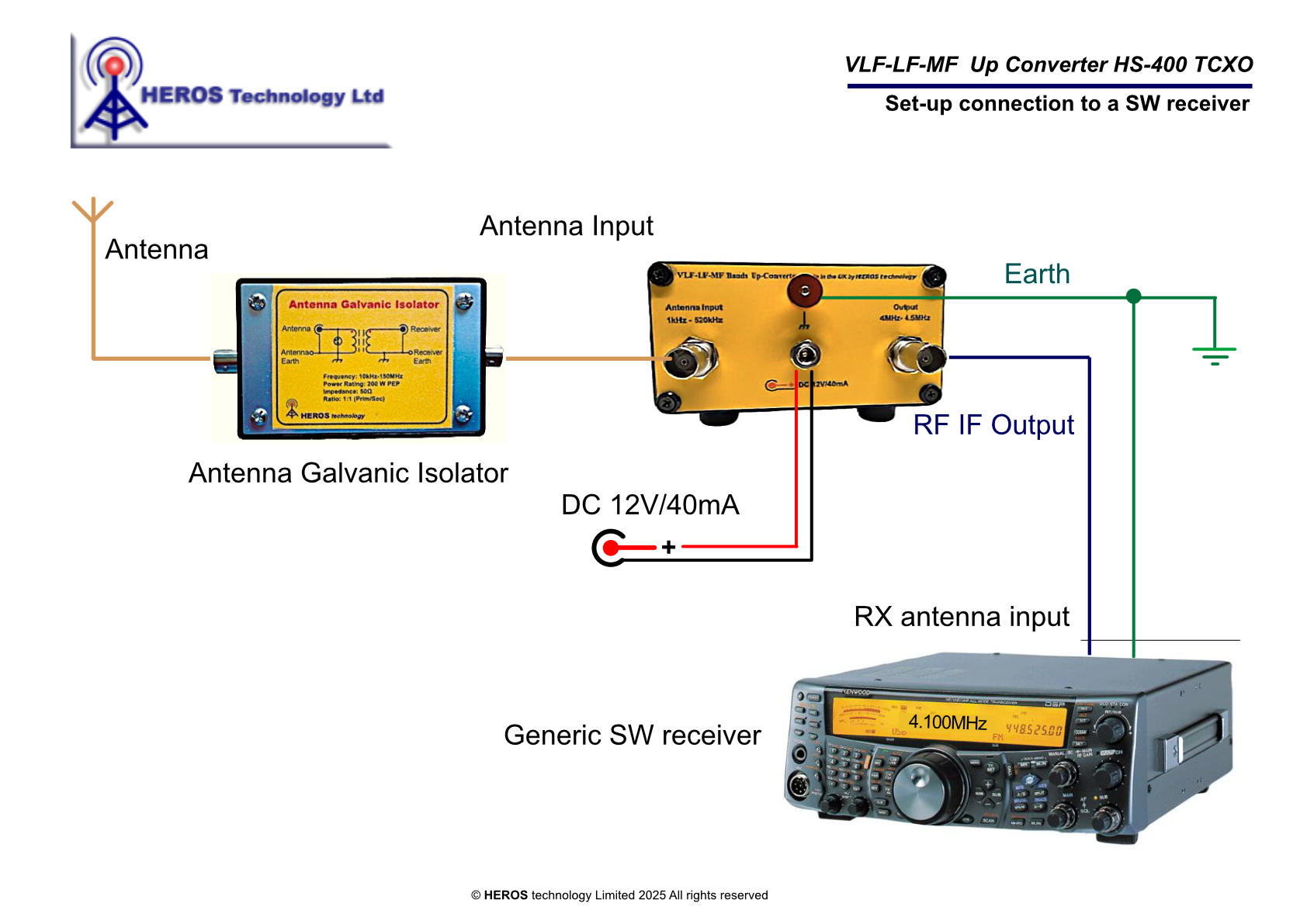
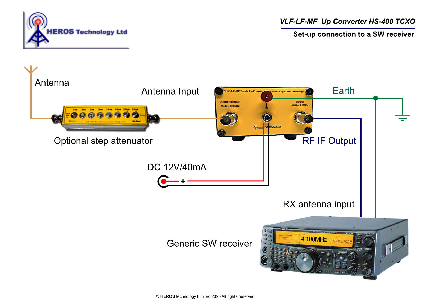
The Up-Converter is designed to be plugged between the antenna and any analogue or software-defined radio (SDR) shortwave receiver operating in the 4.000–4.530 MHz range. It shifts the incoming spectrum from DC–530 kHz up to the 4.000–4.530 MHz band.For example, tuning the shortwave receiver 4.135.500MHz, you are receiving 135.500kHz, just ignoring the digit “4” on the dial.
Software Define Radio (SDR) receivers let customise the dial by the user, as an example see below page "PowerSDR configuration".
.
Introducing the VLF LF MF bands Up-Converter
The annual transmission event on the Alexanderson Day with the Alexanderson Alternator from 1924 on VLF band 17.2 kHz mode CW with the call sign SAQ, on 4 July 2021. Recorded by M0WWA in London on 4 July 2021.
Station equipment:
- Long Wire antenna.
- Longwire Antenna Impedance adapter ; HST-210N ;Heros Technology
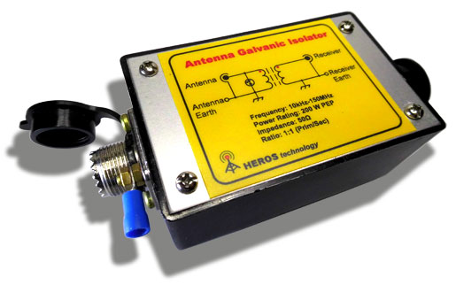
- Antenna Galvanic Isolator HS-100B; for local noise suppression; HerosTech
- VLF-LF-MF up converter HerosTech HS-400, IF output 4MHz-4.5MHz.; HS-400
- Flexradio1500 as IF receiver,
- GPS reference clock from Leo Bodnar
- Power SDR 2.8.0 from KE9NS
"The Big Jump"
"Alexanderson Day" special transmission on 17.2 kHz from SAQ Grimeton radio station in Sweden was received in Granby QC Canada (FN35RK) on 28 June 2015. Distance 5.700 km (3.600mi)
This was the group effort of VE2CRG,the Granby Amateur Radio Club.
The radio station setup included a tuned 1.7m diamond loop, FET balanced preamplifier, Heros Technology VLF-LF Up- Converter model-400, multiband IF receiver tuned on 4.017 MHz and Spectral Analysis software Spectran v2.
- Type: TCXO Temperature Compensated Crystal Oscillator
- Frequency:4.000MHz, fundamental
- Frequency accuracy: ± 0.1ppm @ 25±3°C
- Phase noise: -135dbc/Hz @ 1KHz
- Operating temperature: -10°C to +60°C
- Frequency Stability: ±0.5ppm @ 25°C
- Ageing: ±3ppm typical per year.
Power: DC 12volts/40mA max
Enclosure: Aluminium
Size: 125mmx105mx55mm ( 4.921x4.133x2.165in)
Weight: 480g Shipping Weight: 800g
Country of origin: Designed & manufactured in the United Kingdom.
Operating
The VLF-LF Up-Converter HS-400 TCXO is suitable for use with active antennas, loop antennas and preamplifiers providing an output impedance of 50 Ω.
The antenna input port is DC protected, allowing the connection of active antennas powered through their feeder coaxial cable.
Beverage antennas may need a 50 Ω matching network device for best performance.
WARNING!
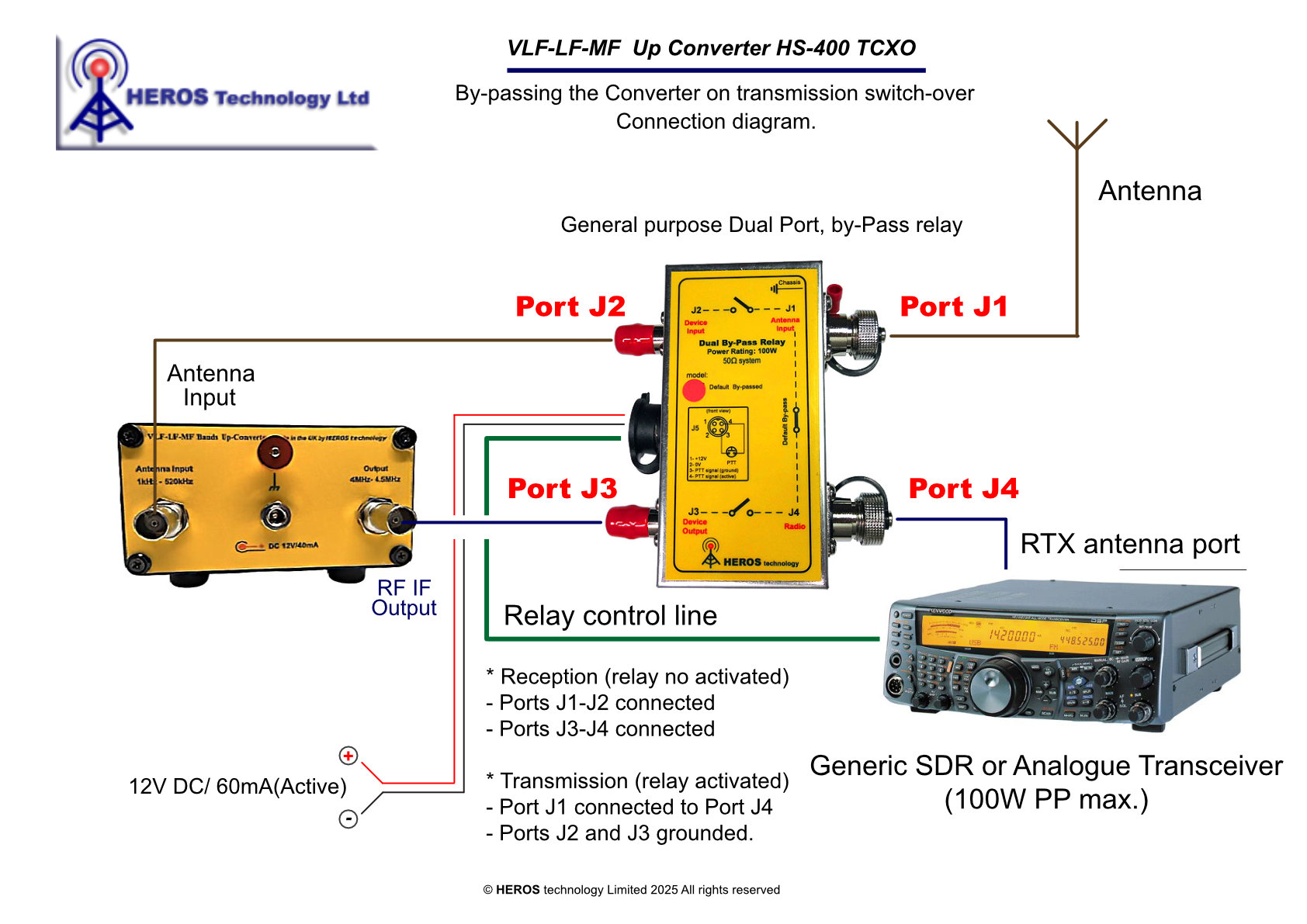
If the VLF-LF up-Converter is connected in line to a HF transceiver acting as IF receiver, take precautions to prevent transmitting any signal into the converter.
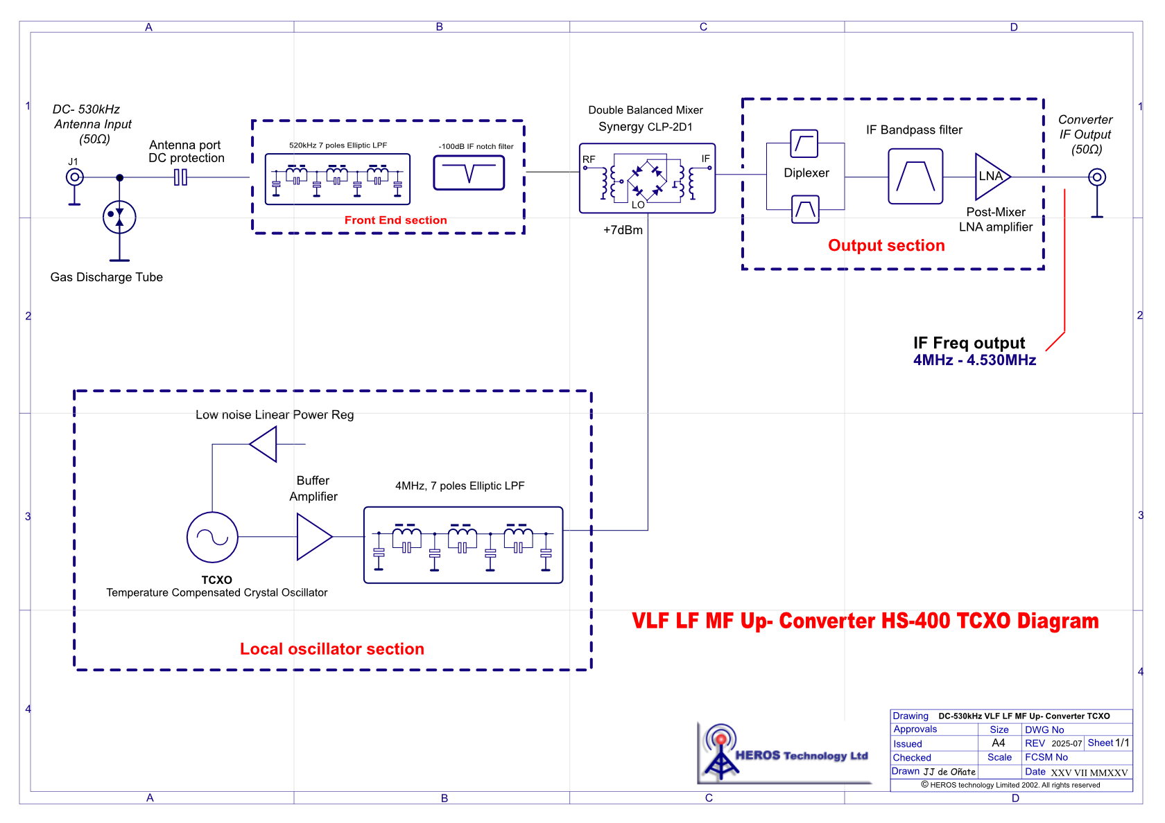
Referring to the above functional blocks diagram, the 50 Ω antenna is connected to J1 ,BNC type connector; a Gas Discharge Tube protects the converter from transients that may come from the antenna. DC protected. Compatible with active antennas powered through their feeder coaxial cable.
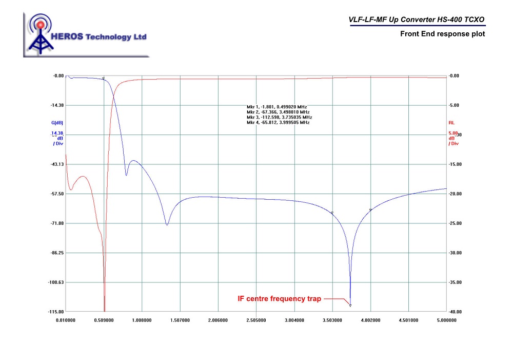
Next the input filters section is a combination of a 110dB IF trap and a 7th order, 0.3dB insertion loss, Elliptic Low Pass Filter with a cut-off frequency of 530 kHz.
This section provides good performance right up to the start of the AM broadcast band with a sharp roll-off, giving a good rejection to MW broadcast signals avoiding introducing overload or intermodulation products in the receiver.
VLF-LF-MF Up-Converter HS-400 TCXO
front end response plot.
Local Master TCXO Oscillator
A low phase noise, TCXO provides +7dBm signal level to the mixer
- Type: TCXO Temperature Compensated Crystal Oscillator
- Frequency: 4.000MHz, fundamental
- Frequency accuracy: ± 0.1ppm @ 25±3°C
- Phase noise: -135dbc/Hz @ 1KHz
- Operating temperature: -10°C to +60°C
- Frequency Stability: ±0.5ppm @ 25°C
- Ageing: ±3ppm typical per year.
A low noise linear LDO IC regulates the voltage applied to the oscillator to enhance stability.
The oscillator is followed by an internal buffer stage to improve its stability. Next, an amplifier accommodates the signal to the required level. It connects to a 4 MHz, 7th order, Elliptic Low Pass Filter which cleans up any harmonics and assures that a pure signal applies to the mixer to minimize spurious responses.
Mixer
The mixer stage is designed around a Synergy CLP-2D1 double balanced mixer. It is rated to operate from DC to 10 MHz, giving and excellent frequency coverage. Designed for +7 dBm of LO power, it have a conversion loss of less than 5 dB at VLF LF bands, which is compensate by the post-mixer amplifier. A double balanced mixer has the advantage of high port-to-port isolation, which keeps the strong LO signal from degrading the dynamic range of the IF receiver. Every effort has been made to terminate the ports of the mixer in a proper 50 Ω impedance to maximize its performance.
The mixer IF port is most critical in terms of proper termination, for so, a diplexer circuit provides a 50 Ω resistive load to the mixer while passing the desired signal to the IF amplifier, with minimum loss.
Next, a Band Pass filter at IF frequency connects to a Low Noise Amplifier to compensate losses, delivering around 5dB of gain to the output, necessary to overcome losses from external cable tails, relays and connectors.
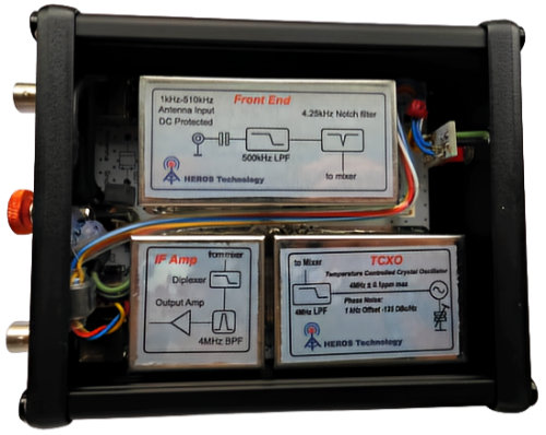
Design
A carefully PCB and shielding design keep feed through signals of the HF receiving frequency down to a very low level; therefore, weak LF signals will not be interfered by strong HF signals on the same frequency.
The HF receiver used should have strong rejection of HF signals through paths other than the antenna connector. Most HF transceivers and receivers have good performance in this respect, but some SWL receivers do not and may be used with the addition of filters and shielding.
Recommended accessories
10KHz to 150MHz Antenna Galvanic Isolator.
Removes ground loops.
Rejects pick-up noise from the antenna feedline.
Specifically recommended to work on VLF,LF, MF bands.
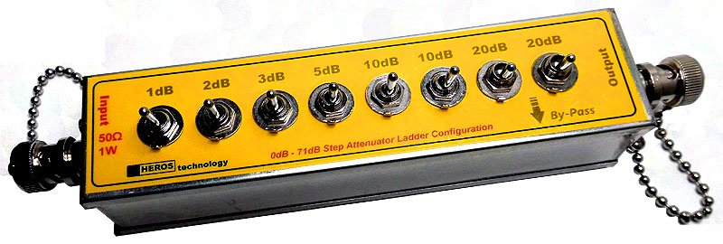
0 - 71 dB Step Attenuator Ladder Configuration
The step attenuator is ideally suited for safeguarding the front-end of receivers or serving as a calibrated attenuator for the evaluation of receiving performance. It is an invaluable instrument for the precise management of amplitude levels. Furthermore, it enhances the impedance match between devices that are sensitive to impedance variations, such as amplifiers, oscillators, and filters. By offering isolation between impedances, it effectively reduces the Voltage Standing Wave Ratio (VSWR) of components connected in a cascaded configuration.
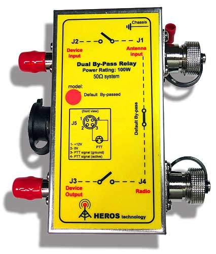
General purpose LF-HF-VHF-UHF, Dual Port, by-Pass relay
- 100 Watts RF power rating
- DC - 1300MHz
The device is engineered to bypass the Input and Output RF ports of any equipment that is in the signal path of your transceiver or transmitter. A common application for this device is its integration between the antenna and a transceiver or transmitter, with a preselector, preamplifier, or filter system. Upon engaging the transmission, either through the Push-To-Talk (PTT) function or via the keying line, the Input and Output RF ports of the device are bypassed, thereby preventing any risk of overload.
The set includes:
VLF-LF-MF Up-Converter, user manual in CDROM format, two BNC-BNC coaxial cable tails, power supply cable with EMI filter with auxiliary connectors.