| |
Two Way 0º Passive Reciprocal Splitter-Combiner |
|
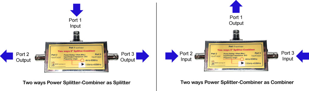
The Two Way 0º Splitter-Combiner is a reciprocal passive electronic device that arranges one common input/output port and two independent bidirectional ports.
The Reciprocal Splitter-Combiner performs two different functions depending on how it is connected.
As Splitter:
It accepts an input signal and delivers two output signals with specific phase and amplitude characteristics as follows:
- Equal amplitude
- 0° phase relationship between any two output signals
- High isolation between output signals
- Low insertion loss
As Combiner:
Since the 0° power splitter is a reciprocal passive device it may be used as a power combiner simply by applying signals into each of the splitter output ports.
The vector sum of the signals will appear as a single output at the splitter input port.
NOTICE that the Combiner is not a frequency mixer due its linear behaviour and thus does not produce further frequency products.
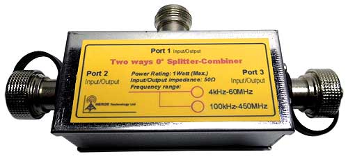
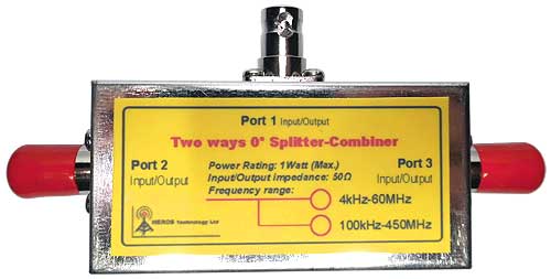
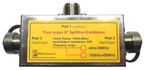
The Two Way 0º Passive Reciprocal Splitter-Combiner is available in several connector options. See table below. |
| |
 |
| |
|
|
(click to enlarge) |
|
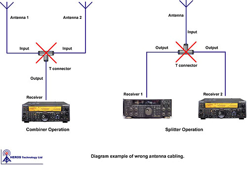
Why we need a Splitter-Combiner
The basic form of a splitter is a simple "T" shape connection, which has one input and two outputs as shown in the figure. The arrangement is very simple but it will not work properly due two important limitations, poor isolation and impedance mismatch.
Suppose, for example, that two antennas were fed to a receiver input using a simple "T" arrangement connection as a combiner. If one antenna appears as a short at its resonant frequency, it would cancel the other antenna and, in effect, wipe out signals at the receiver input. Also the resultant impedance will be the parallel combination of all impedances connected to the “T” arrangement, far from the 50 Ohms nominal.
If instead a “T” arrange connection a proper Splitter-Combiner is used it would provide high isolation between input ports so that the antenna "short condition" at one input port would have little influence on the other input port. In addition no mismatch condition will occur avoiding desensitisation, intermodulation distortion (IMD), and other undesirable effects due impedance mismatch.
Other important performance of the Splitter-Combiner due its high port isolation is avoiding coupling between receivers sharing the same antenna. This is especially important when SDR receivers are used due their tendency to radiate back to the antenna spurious signals. |
| |
|
|
| |
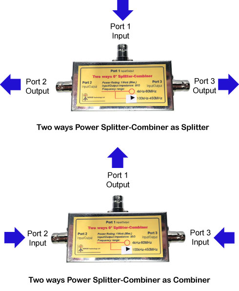
Reciprocal operation modes |
|
| |
|
|
 |
|
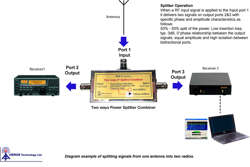
Splitter Operation
When a RF input signal is applied to the common port it delivers two signals on the bidirectional ports with specific phase and amplitude characteristics as follows:
50% - 50% split of the power, Low insertion loss, typ. 3dB, 0°phase relationship between the output signals, equal amplitude and high isolation between bidirectional ports. |
| (click to enlarge) |
|
|
| |
|
|
| |
|
|
 |
|
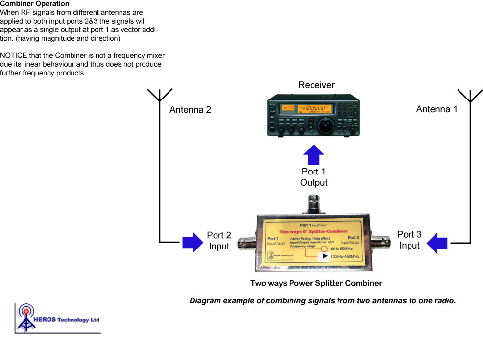
Combiner Operation
Conversely when RF signals from different sources are applied to both bidirectional ports the signals will appear as a single output at the common port as vector addition. (having magnitude and direction).
NOTICE that the Combiner is not a frequency mixer due its linear behaviour and thus does not produce further frequency products. |
| (click to enlarge) |
|
|
| |
|
|
| |
|
|
 |
|
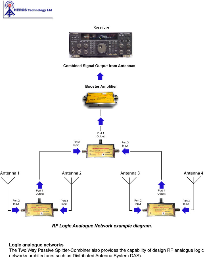
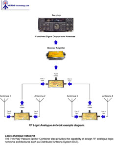
Logic Analogue Networks
The Two Way Passive Splitter-Combiner also provides the capability of design RF analogue logic networks architectures such as Distributed Antenna System (DAS). |
(click to enlarge) |
|
|
| |
|
|
| |
| |
|
|
|
|
| |
VLF- LF-MF-HF model features:
- Operating frequency: 4kHz to 60 MHz
- RF Power Rating: 1 Watt (Max)
- Impedance: 50 Ohms
- Insertion Loss (dB): Type Max.
0.004 - 0.04 MHz: 0.3 0.6
0.04 - 30 MHz: 0.3 0.6
30 - 60 MHz: 0.6 1.0
- Isolation (dB): Type Min.
0.004 - 0.04 MHz: 27 20
0.04 - 30 MHz: 30 20
30 - 60 MHz: 27 20
- Phase Unbalance:
- 0.004 - 0.04 MHz: 2.0 (Max)
- 0.04 - 30 MHz: 3.0 (Max)
- 30 - 60 MHz: 4.0 (Max)
- Amplitude Unbalance:
0.004 - 0.04 MHz: 0.15 dB (Max)
0.04 - 30 MHz: 0.25 dB (Max)
30 - 60 MHz: 0.30 dB (Max)
|
|
LF-MF- HF-VHF-UHF model features:
- Operating Frequency: 100kHz to 450 MHz
- RF Power Rating: 1 Watt (Max)
- Impedance: 50 Ohms
- Insertion Loss (dB): Type Max.
0.1 - 1 MHz: 0.2 0.6
1 - 200 MHz: 0.4 0.75
200 - 400 MHz: 0.6 1.0
- Isolation (dB): Type Min.
0.1 - 1 MHz: 20 15
1 - 200 MHz: 25 20
200 - 400 MHz: 25 20
- Phase Unbalance:
0.1 - 1 MHz: 2.0(Max)
1 - 200 MHz: 3.0 (Max)
200 - 400 MHz: 4.0 (Max)
- Amplitude Unbalance: 0.3 dB (Max) |
|
|
|
| |
|
|
| |
Enclosure Dimensions: (Without connectors protrude)
Depending on connector choice:
Low profile version N and BNC connector option.
Size: 74x37x30mm (2.913x1.457x1.181in)
Standard version SO-239 connector option.
Size: 74x37x40mm (2.913x1.457x1.575in)
|
|
| |
|
|
| |
Two Way Reciprocal Passive Splitter-Combiner options |
|
| |
|
|
| |
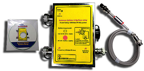
All models include:
Passive Reciprocal Splitter-Combiner and user manual in CDROM format.
* Other connector options available, please ask. |
|
|
|
|
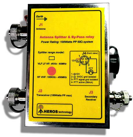
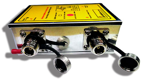
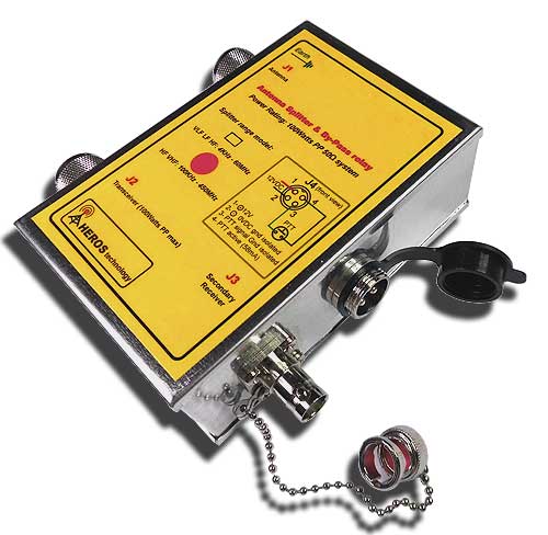
Antenna-Signal Splitter & By-Pass Relay
| |
The Antenna Splitter & By-Pass Relay combines any transceiver with any receiver sharing the same antenna, enabling simultaneous reception feature on both radios.
Simultaneous reception on any transceiver and any receiver sharing the same antenna.
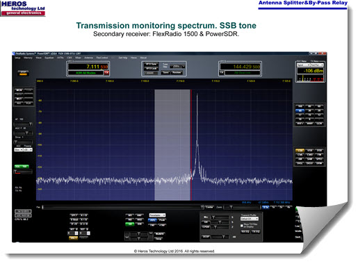
If a SDR radio is used as secondary receiver you get Panoramic Spectrum reception/Transmission monitoring feature.
On transmission switch-over embeded protection circuitry avoids overloading the secondary receiver and internal components of the unit.
It brings new life to any older radio by adding advanced SDR features.
High performance, low insertion loss, telecommunication grade set of relays rated for RF power applications are used in order keep large isolation among ports and the nominal 50 Ohms impedance.
Two models are available depending on the range of frequencies covered by the passive splitter device:
VLF- LF-MF-HF: 4kHz - 60MHz.
LF-MF- HF-VHF-UHF: 100kHz - 450MHz
|
|
| |
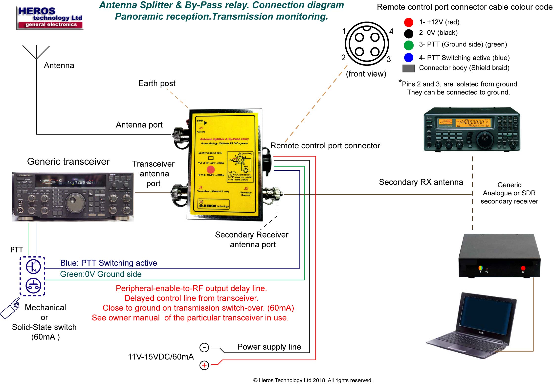
Antenna Splitter-By-Pass relay operation
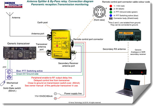
The Antenna Splitter-By-Pass relay device is inserted between the antenna and a transceiver, a secondary receiver is connected to the corresponding port.
By default the Antenna Splitter-By-Pass relay device is in reception state enabling reception on both radios. When the transceiver transmit/receive switching (PTT or CW key) is pressed the RF outputs after some milliseconds delay time called “Peripheral-enable-to-RF output”.
This RF output delay time is used to give enough time to engage the internal relays of the Antenna Splitter & By-Pass Relay device before the RF power outputs the transceiver.The
delay time varies depending on the transceiver settings.
Some popular transceivers “Peripheral-enable-to-RF output” default delay time are as follows:
Kenwood TS-480/2000: 10ms
Yaesu FT-1000 MKV/Filed: 5ms
Yaesu FTDX-9000, FT-2000: 15ms
ICOM IC-706: 15ms
ICOM IC-7000: 10ms
Elecraft K3: 8ms
TenTec Orion/OmniVII: 15ms
TenTec OmniVII & Orion I/II: 15ms
To work with the Antenna Splitter & By-Pass relay we recommend to set the delay to 20-30ms. See owner manual settings of the particular transceiver in use.
Remote Control
An output enable SEND control signal from the transceiver is activate (type sink to ground) BEFORE the Peripheral-enable-to-RF output delay time starts.
The output enable SEND control signal is generally available on a service connector located on the rear panel of the radio.
Transceiver manufactures give different names to the output enable SEND control signal as SEND, DELAY, LINEAR AMPLIFIER, TX-GND, T/R-LINE, etc. See owner manual of the particular transceiver in use.
IMPORTANT WARNING TO AVOID DAMAGE
- Before apply RF power to the unit make sure that all connections are right and the device is powered.
- First test switching functionality without RF power.
- If the output enable SEND control signal is not connected or the Peripheral-enable-to-RF output delay time is to short the RF power coming from the transceiver will reach the device still in reception state (relays no engaged) damaging the internal splitter component and may be the secondary receiver.
- Check-up that the enable output SEND control signal from the transceiver in use is the default standard on most transceivers called “Closing to Ground”, “Sink to Ground”, “Sink Current”, or “Ground on Transmit” (denomination may vary).
- Some transceivers may output a non-standard “+12V” enable SEND control signal instead of the standard Closing to Ground “one. In this case the Antenna Splitter-By-Pass Relay device WILL NOT WORK.
- The maximum peak sink current to activate the Antenna Splitter & By-Pass relay device is 100mA. It is compatible with relay or solid-state, closure to-ground, type of output ports.
Heros Technology Ltd disclaims all liability arising from this information and its use.
It is user responsibility to ensure that your application meets with specifications.
|
|
|
|
|
Connection diagram.
(click to enlarge) |
|
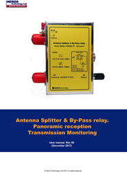
Antenna Splitter & By-Pass Relay. User manual. |
|
|
 |
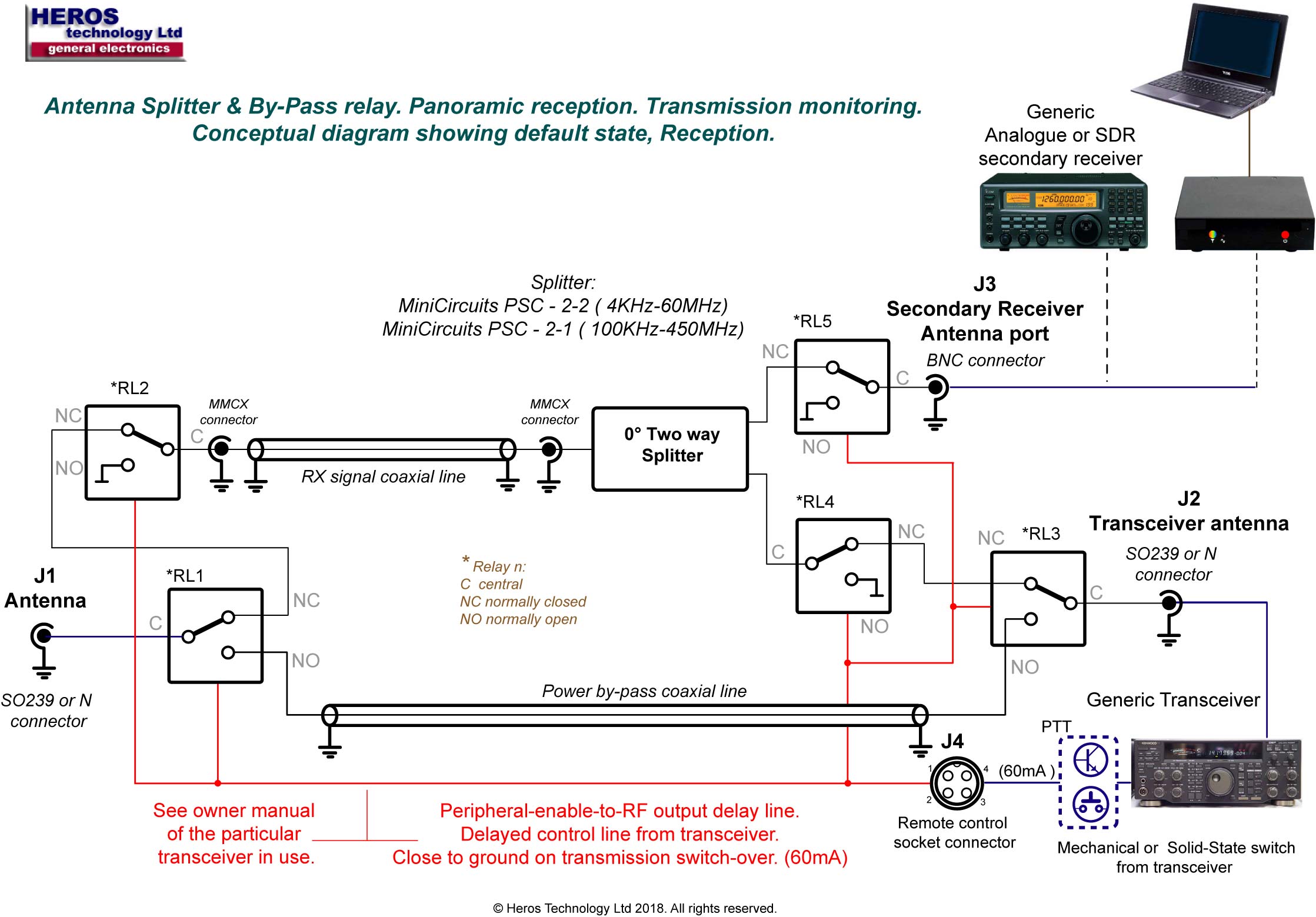
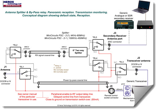
Conceptual diagram
(click to enlarge)
|
|
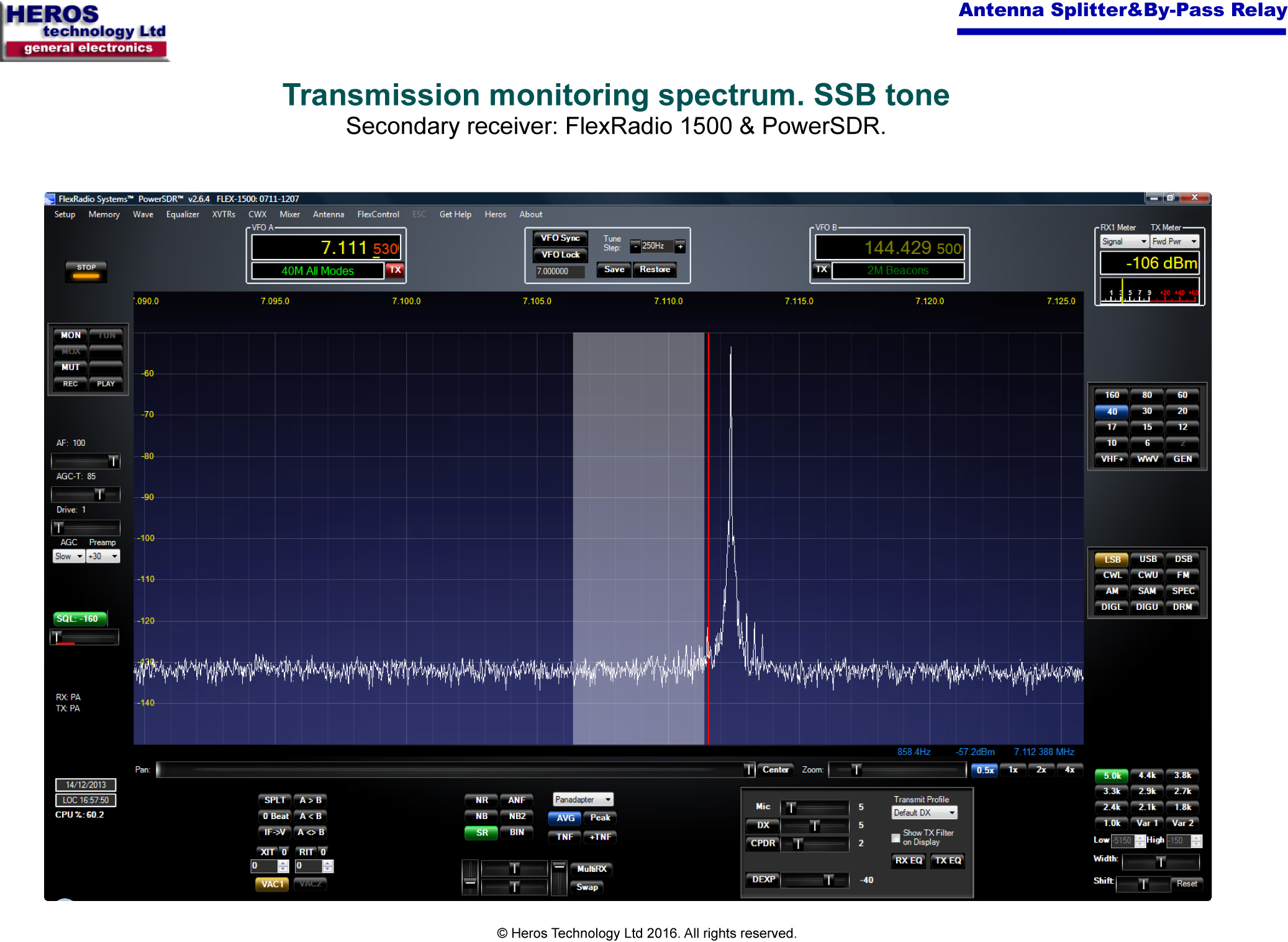
Transmission monitoring using a SDR secondary receiver. SSB tone.
(click to enlarge)
. |
Splitter LF-MF- HF-VHF-UHF model features:
- Operating Frequency: 100kHz to 450 MHz
- RF Power Rating: 1 Watt (Max)
- Impedance: 50 Ohms
- Insertion Loss (dB): Type Max.
0.1 - 1 MHz: 0.2 0.6
1 - 200 MHz: 0.4 0.75
200 - 400 MHz: 0.6 1.0
- Isolation (dB): Type Min.
0.1 - 1 MHz: 20 15
1 - 200 MHz: 25 20
200 - 400 MHz: 25 20
- Phase Unbalance:
0.1 - 1 MHz: 2.0(Max)
1 - 200 MHz: 3.0 (Max)
200 - 400 MHz: 4.0 (Max)
- Amplitude Unbalance: 0.3 dB (Max) |
General features:
- Frequency range:
Model VLF- LF-MF-HF: 4kHz - 60MHz
Model LF-MF- HF-VHF-UHF: 100kHz-450MHz
- Insertion loss Reception: 3dB
- Insertion loss Transmission: < 0.5dB
- RF Power rating Transmission: 100 W PP max.
- Impedance: 50 Ohms.
- Power Splitter device:
VLF-LF-MF-HF: Mini-Circuits
PSC-2-2+
LF-MF-HF-VHF: Mini-circuits
PSC-2-1+
- Relays switching time:
- Set: 5mS
- Reset: 4mS
- Activation port: Sink to ground (100mA max)
- Diode protection.
- Power supply: 11-15 Volts DC/60 mA (activated)
- Size: 73x110x40mm(2.87x4.33x1.57in)
- Connectors: SO-239 (LF) or N type (VHF) Antenna and Transceiver;
BNC receiver output.
- Remote Control cable :
Connector type: Foster 4 vias. Shielded control cable with snap-on
RFI-EMI suppressor cores included.
Combined type of connector configurations also available. Please ask. |
Splitter VLF- LF-MF-HF model features:
- Operating frequency: 4kHz to 60 MHz
- RF Power Rating: 1 Watt (Max)
- Impedance: 50 Ohms
- Insertion Loss (dB): Type Max.
0.004 - 0.04 MHz: 0.3 0.6
0.04 - 30 MHz: 0.3 0.6
30 - 60 MHz: 0.6 1.0
- Isolation (dB): Type Min.
0.004 - 0.04 MHz: 27 20
0.04 - 30 MHz: 30 20
30 - 60 MHz: 27 20
- Phase Unbalance:
- 0.004 - 0.04 MHz: 2.0 (Max)
- 0.04 - 30 MHz: 3.0 (Max)
- 30 - 60 MHz: 4.0 (Max)
- Amplitude Unbalance:
0.004 - 0.04 MHz: 0.15 dB (Max)
0.04 - 30 MHz: 0.25 dB (Max)
30 - 60 MHz: 0.30 dB (Max) |
| |
|
|
| |
Antenna Splitter & By-Pass relay options |
|
| |
All models include:
Antenna Splitter & By-Pass relay, user manual in CDROM format and EMI filter shielded remote control cable with connector.
* Other connector options available, please ask. |
|
| |
|
|
| |
|
|
| |
|
|
|
| |
|